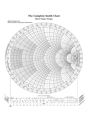
The load impedance is normalized, and the point (0.5 + j0.5) is plotted and shown as point A in Figure 4.13. The input impedance and reflection coefficient can be determined by using the Smith chart. Suppose that a (1/3)λ-long, 50 Ω line is connected to a load impedance of (25 + j25) Ω. For better clarity and practice, it is highly recommended to follow this example by repeating the graphical solution taps on a new Smith chart. The basic operations of the chart can be understood by an example to be discussed next. įigure 4.13 displays a typical commercially available Smith chart. This is useful in oscillator design, where designers routinely have to work with negative resistance values. The use of a compressed Smith Chart therefore allows the designer to visualize device parameters over the complete frequency range, where both positive and negative resistance behavior may be exhibited. From 6 to 10 GHz, the pole lies inside the Γ 3 = 1 boundary of the Smith Chart in Figure 4.10, indicating that negative resistance can be generated in this device using passive shunt feedback. An example of the use of a compressed Smith Chart to plot the negative resistance behavior of an MHG9000 GaAs MESFET, in terms of shunt feedback pole locations (as defined in Chapter 8) on the Γ 3 plane from 2 to 18 GHz is shown in Figure 4.10.


In order to represent negative resistances we need to compress the conventional Smith Chart to be a subset of a larger chart, which typically has a radius of |Γ| = 3.16, this value being chosen to represent 10 dB return gain. Negative resistance values plotted on a Smith Chart lie outside the |Γ| = 1 boundary of the conventional Smith Chart.


 0 kommentar(er)
